


Hello! I am someone who decided to learn embedded systems by my own, however when I was searching for a structured course on BareMetal programming of STM32 I was unable to find any free course. So I am learning it and will share via this and coming blog posts
In this blog you will learn about how to Blink an onboard led of STM32F429I DISCOVERY board which has ARM cortex M4 based uC.
We will be using STM32 cube ide to write code Download it from here st.com/en/development-tools/stm32cubeide.html
Open a new project Click File - New - STM32 In MCU MPU selector search for commercial part number(name of the MCU) mine is STM32F429ZIT6
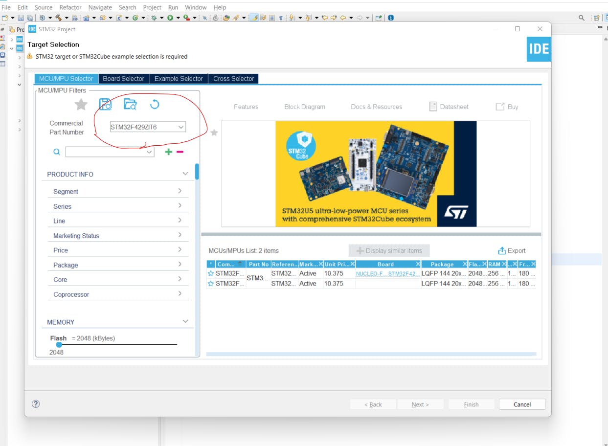
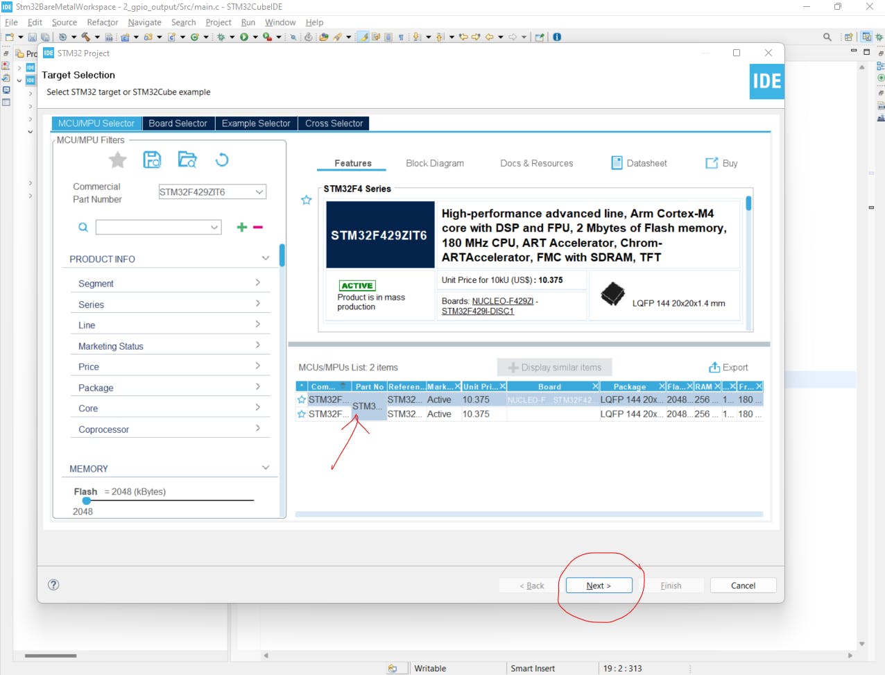
Then select the MCU in the right section and click on next
Give a name to the project and select empty in Target Project type
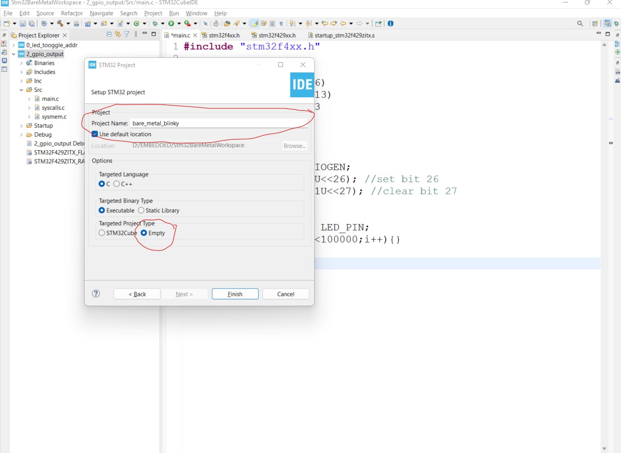
Click Finish
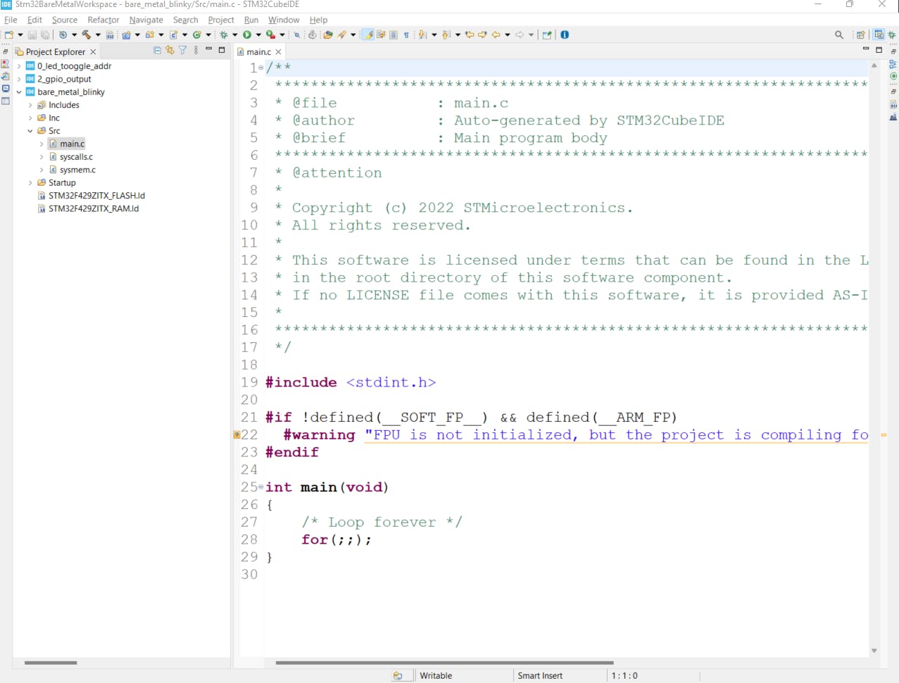
Expand the bare_metal_blinky project that we just created In the Src folder open main.c file
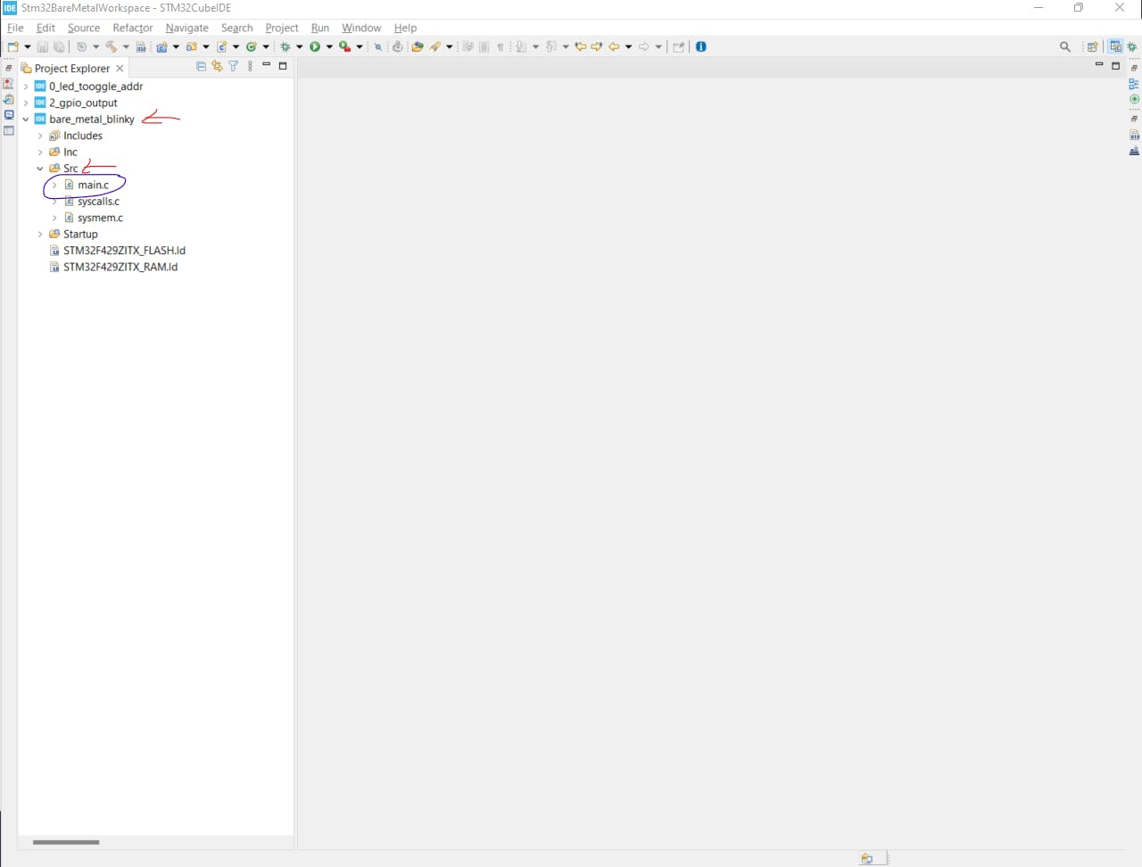
You will see the screen something like this
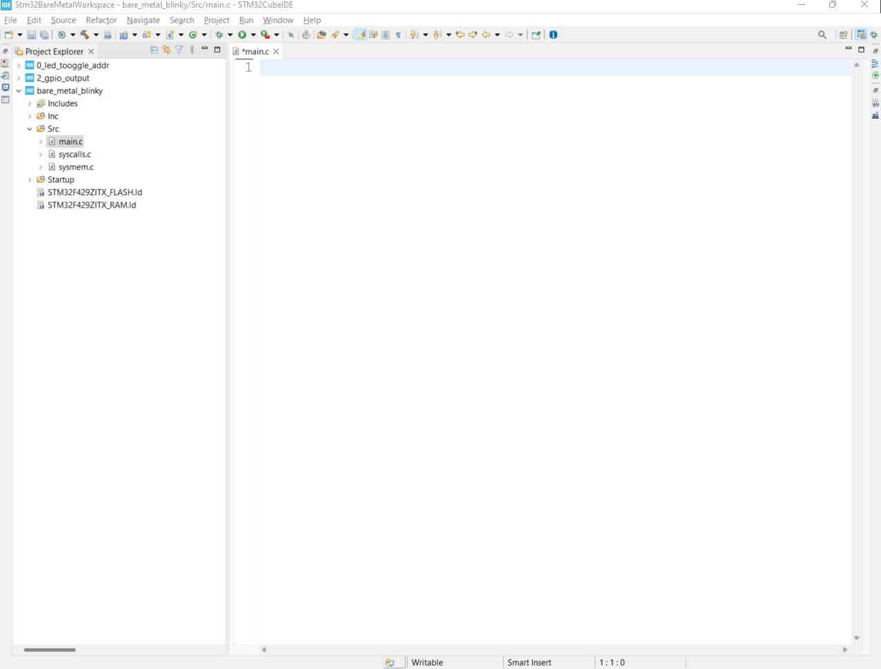
We don’t need any of the content present in the main.c file so we will clear them
Now before moving forward we will have to download few documents and header files
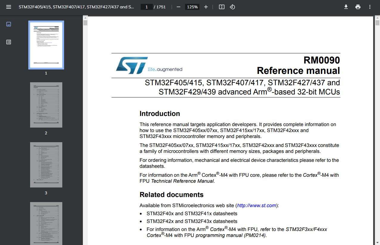
#Documents: 1)Reference Manual for STM32F429 (google according to you uC and download it)
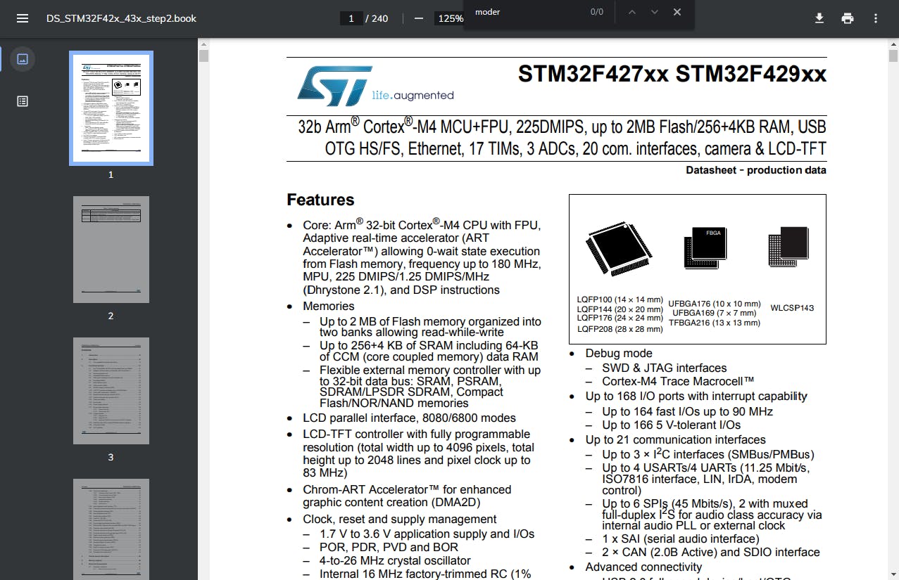
2)Datasheet for STM32F429(google according to you uC and download it)
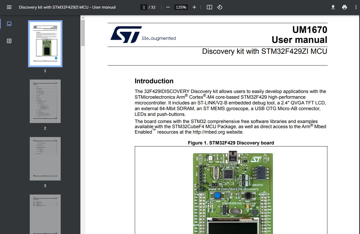
3) User Manual for the board you are using, I am using the discovery kit (google according to the board you are using and download it )
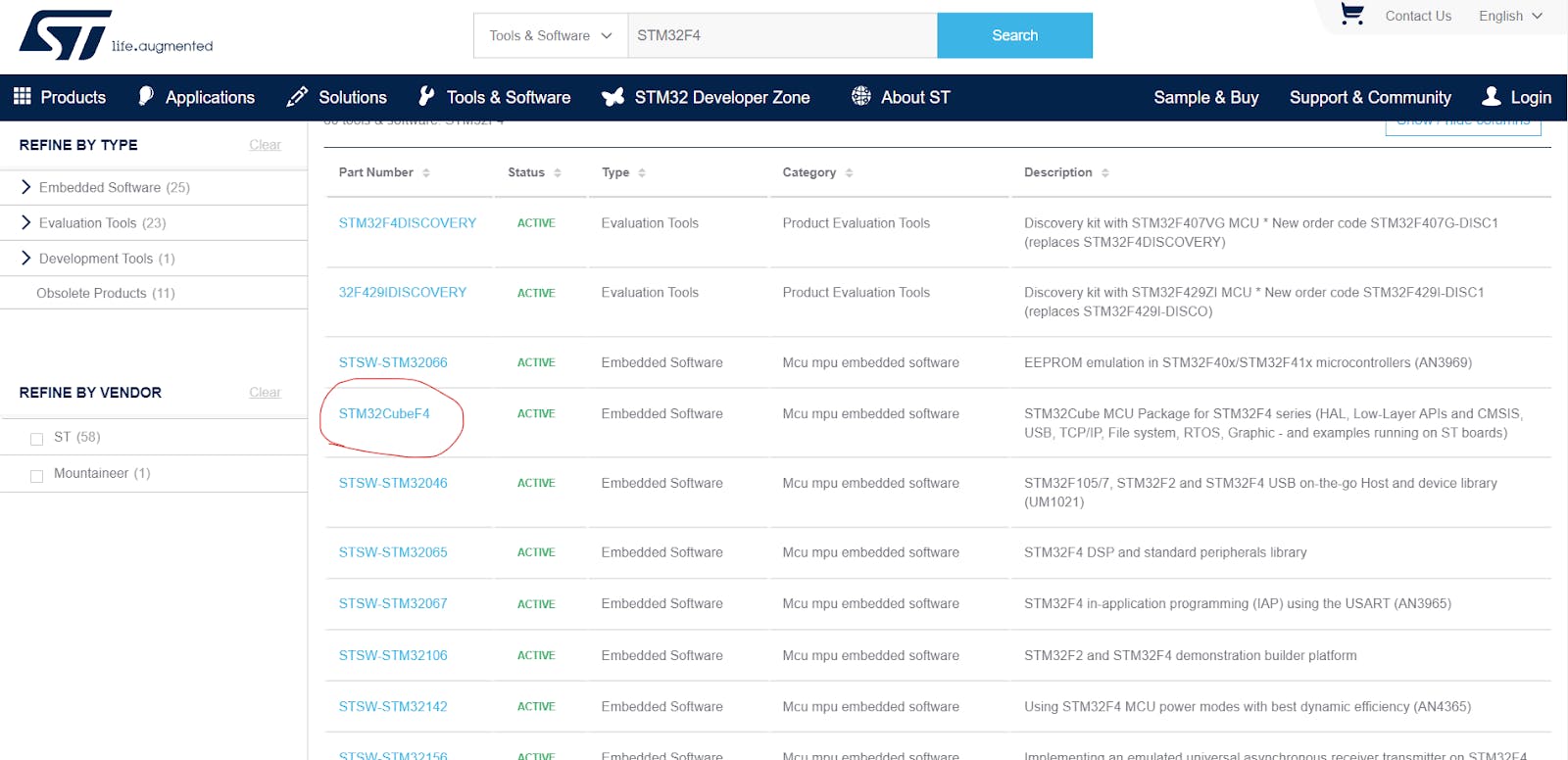
Now Let’s download the header files which we will need to use the registers and write the bare metal code for the blinky 1) Visit the website st.com 2) Select tools and software and search for stm32f4 as shown in the image below (since I have stm32 f4 series mcu, will vary acc to your mcu)

Click on stm32cubef4
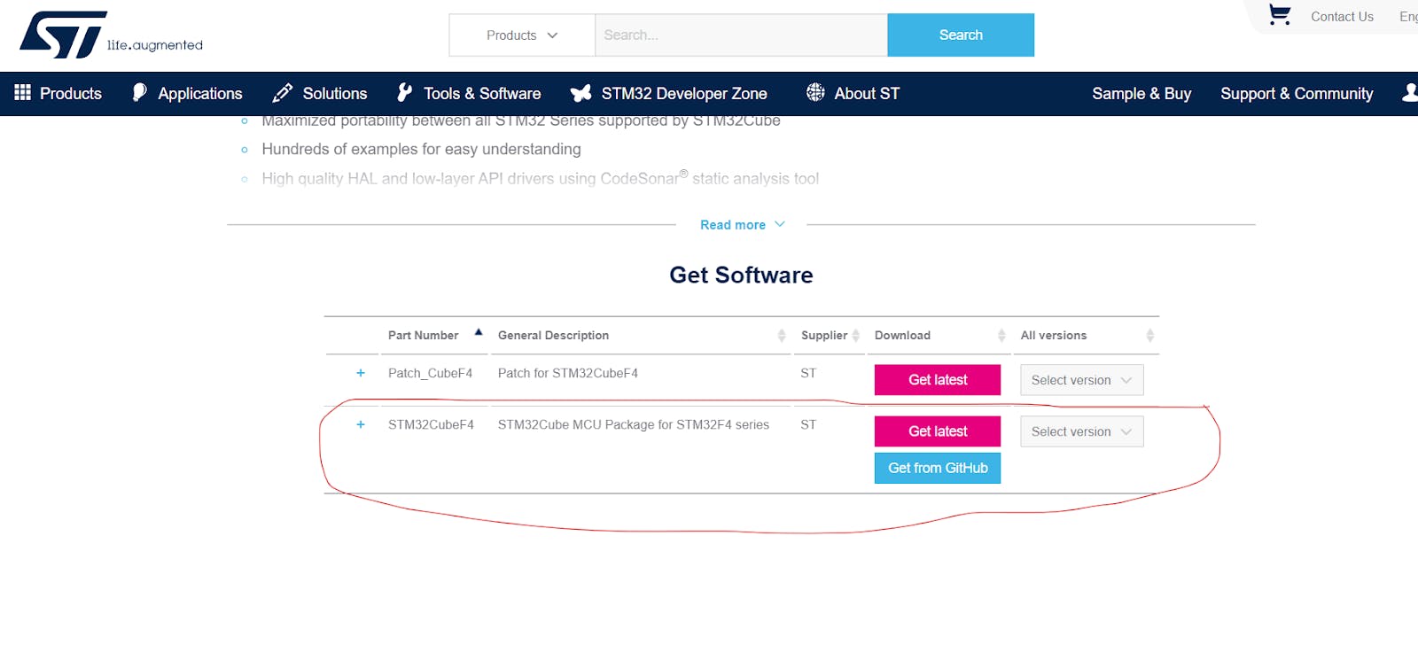
Scroll to the bottom and click on Get Latest as shown in the image or you can download it from GitHub
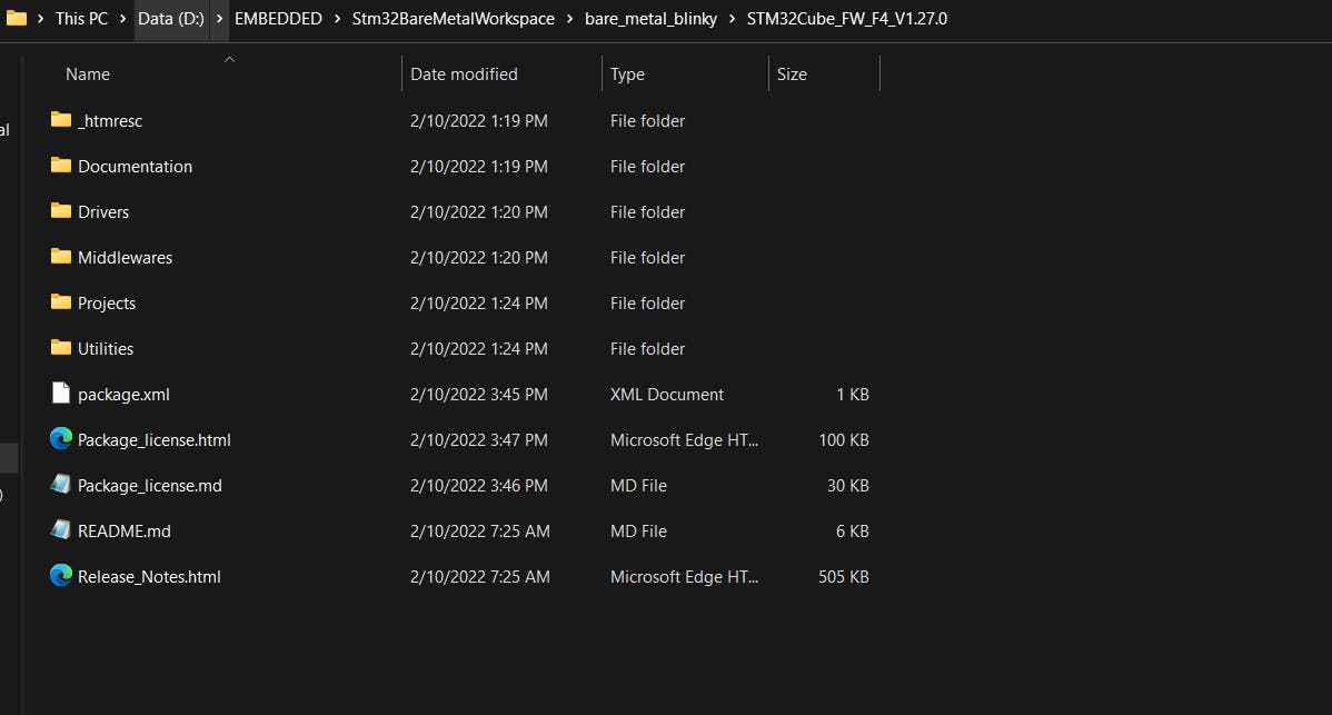
Save the file in the project directory and unzip it (not necessary to save in the project directory but it's nice to have everything organized in the same directory ) You will see the similar contents like this in the directory, most of the files are not required for this tutorial but we will keep it (don’t want to unnecessarily stretch the tutorial )
Now,to use the header file we will have to link the files to our project
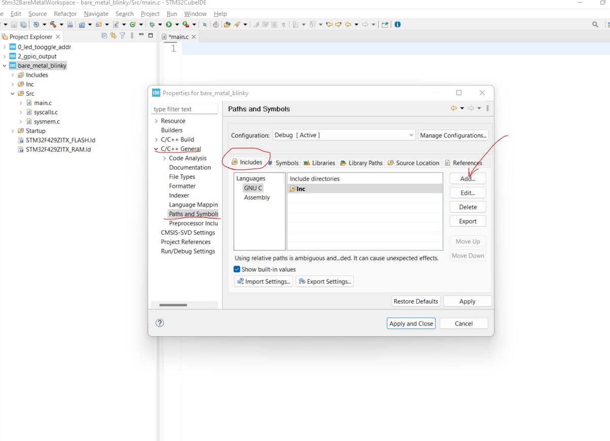
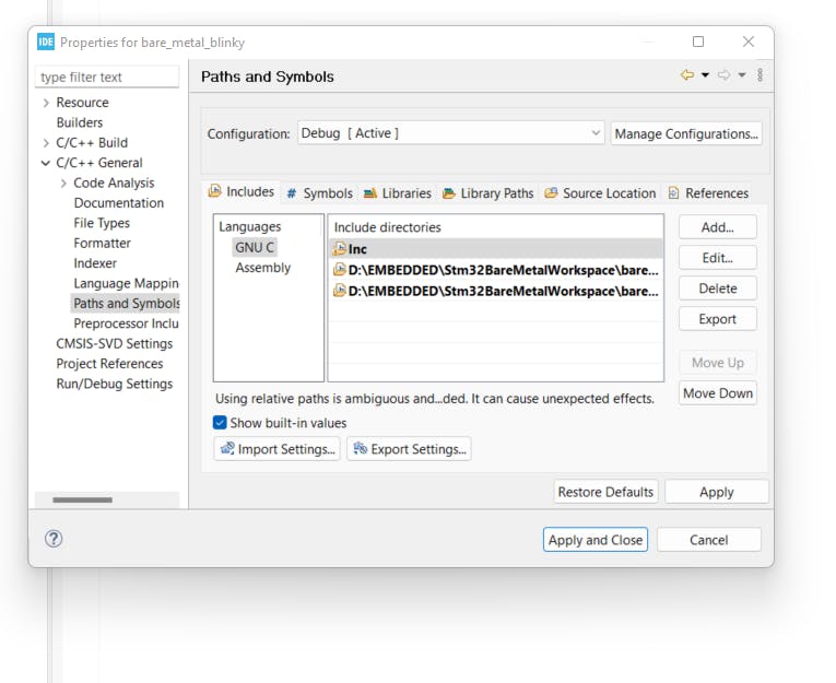
Right click on your project and select Properties Click C/C++ General -- Paths and Symbols -- Includes-- Add (Refer the image below)
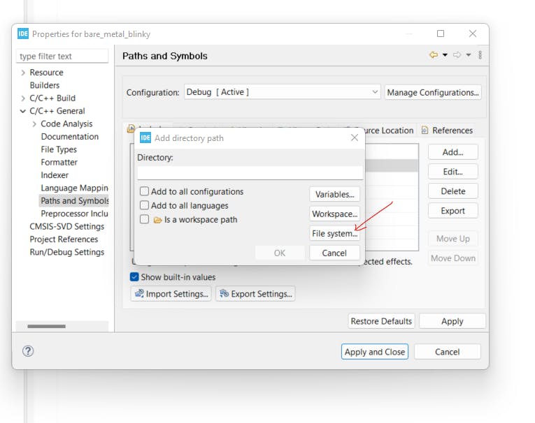
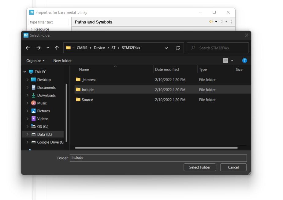
Click File System and navigate to YourProjectDirectory\bare_metal_blinky\STM32Cube_FW_F4_V1.27.0\Drivers\CMSIS\Device\ST\STM32F4xx and select include and click on select folder and then press OK
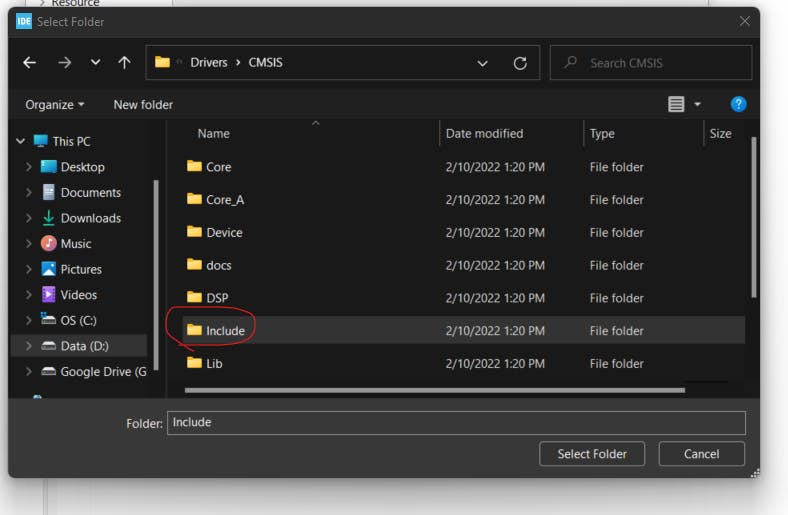
Now do the same process to add include folder present in CMSIS folder
Your Properties box will be similar to this now
Click Apply and close Open main.c file
Add the header file in the main.c file by writing the following statement
#include "stm32f4xx.h"
To Blink the led we have to do the following tasks 1)Figure out the port and Pin where our onboard LED is connected 2)Enable Clock access to that Port 3)Set the Mode of the Pin 4)Switch on the LED 5)Wait for Some Time ‘6)Switch on the LED Repeat Steps from 4 to 6
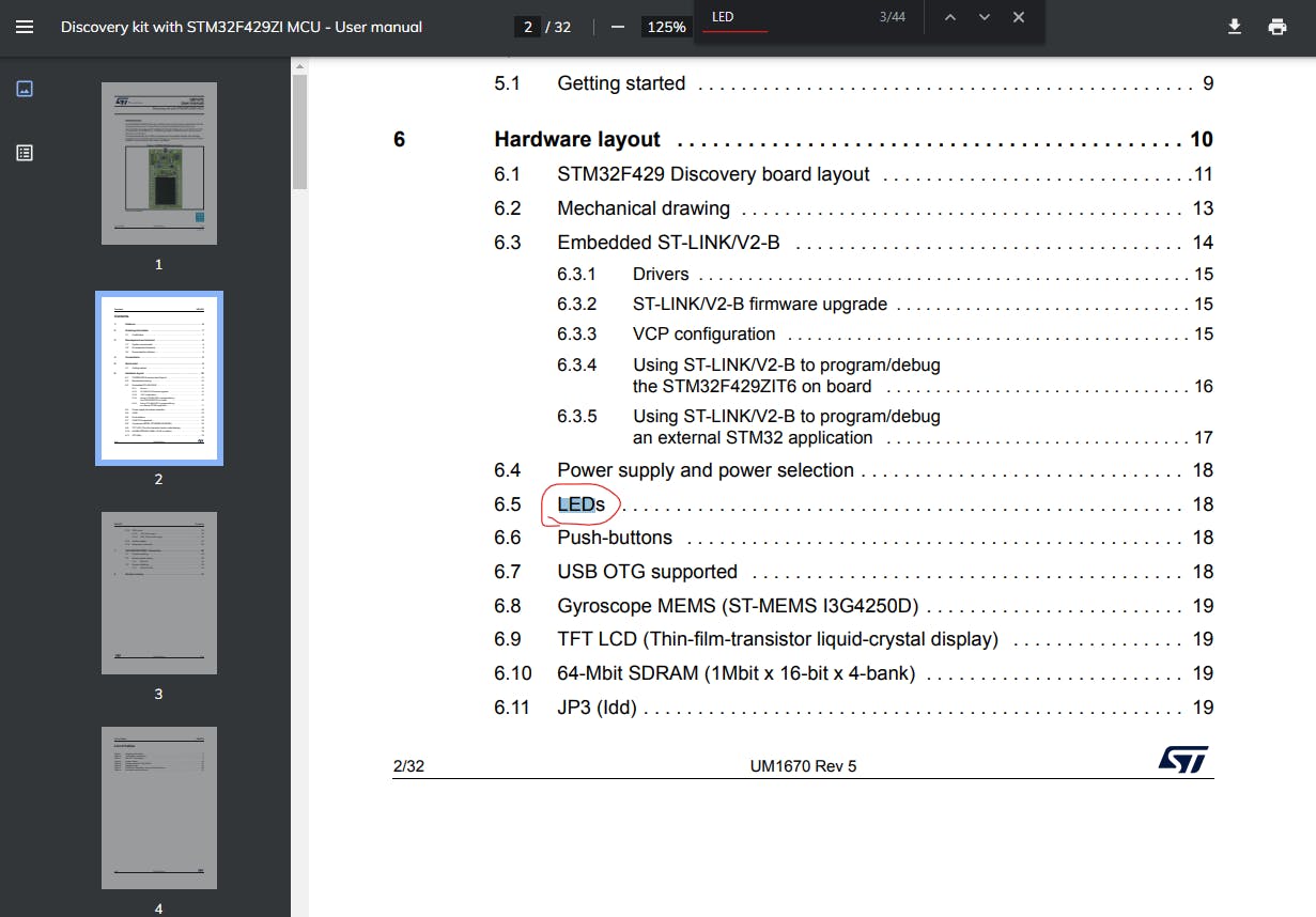
Let's figure out the port at which our onboard led is connected Remember the Board Reference Manual we have downloaded? Open that and press Ctrl+F to search and search led and click on on it to go to that section
So now we know on my board the user LED is connected to Pin PG13 and PG14
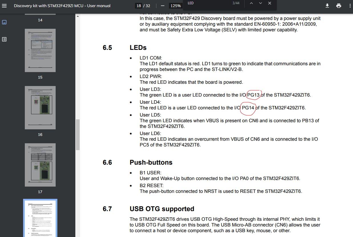
Let's Go with PG13 , in the name PG13 , P stands for port, G is the port name and 13 is the pin number Pins are grouped into Ports such as Port A, Port B, Port C, etc,etc
GPIO ports have at least 2 Registers one is Data Register and one is Direction Register (Also known as Mode Register ) Data Register stores the output state of the Pin (HIGH/LOW) Mode/Direction register is used to set the mode of the pin (INPUT/OUTPUT/some special purpose mode )
Now we know that our Led is connected to port G so we will have enable it by giving clock access to it .
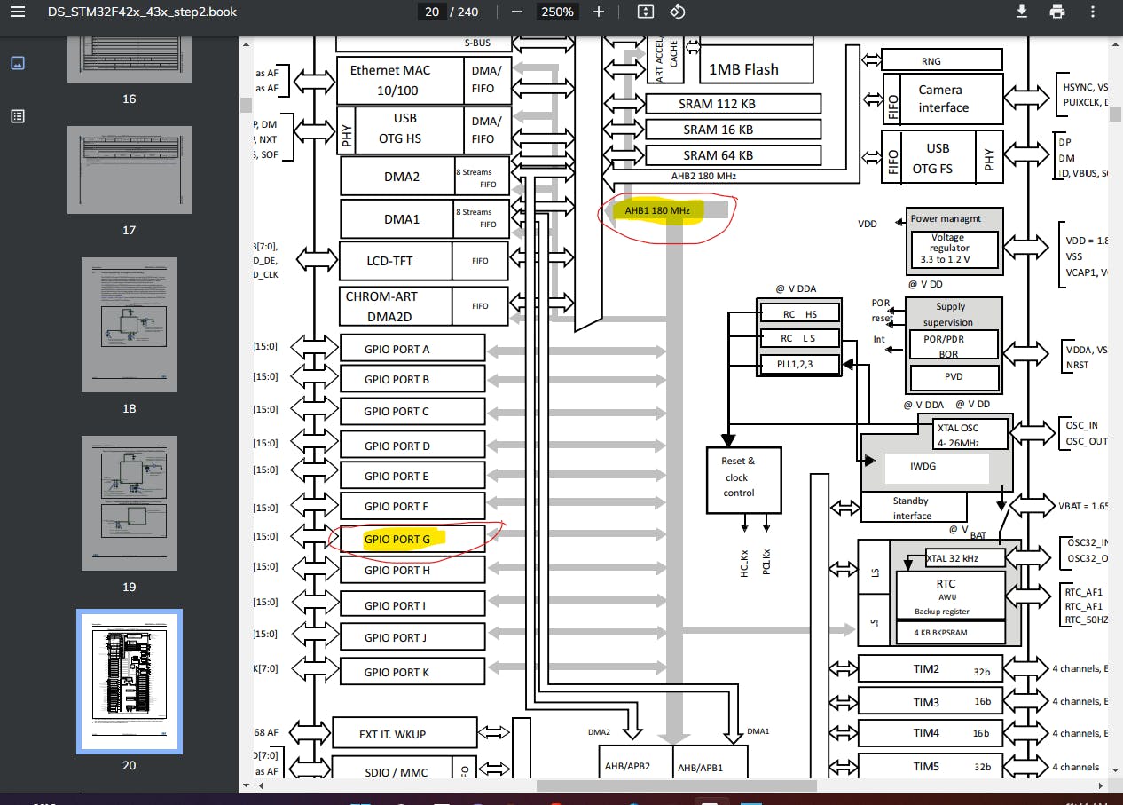
Open the Data Sheet and search BLOCK DIAGRAM
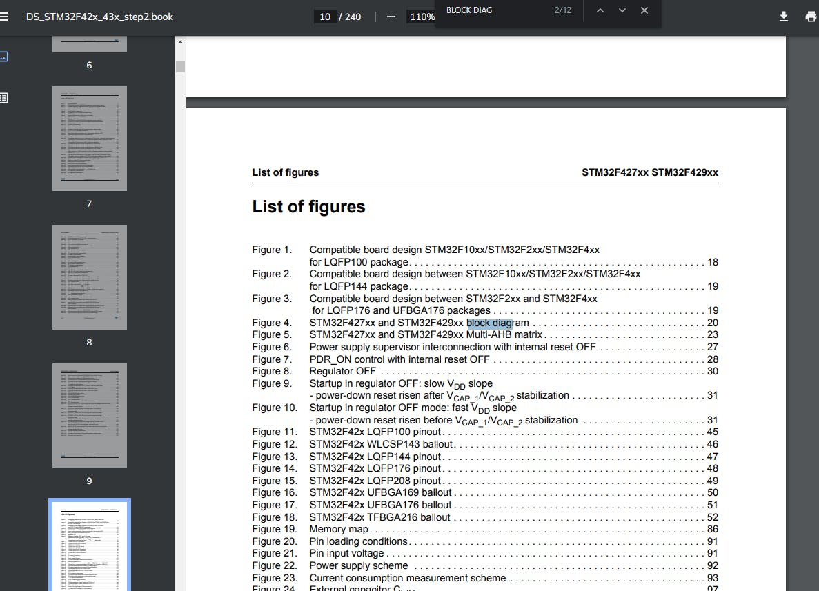
Open the Block Diagram
We can see that the Port G is connected to the BUS AHB1(Advance High Performance Bus)
Which means, BUS AHB1 supplies clock access to the port B Lets Enable the AHB1 bus for port G
Now open the Reference Manual and search the Bus name which is AHB1 in my case
Open the reference manual and Search AHB1EN
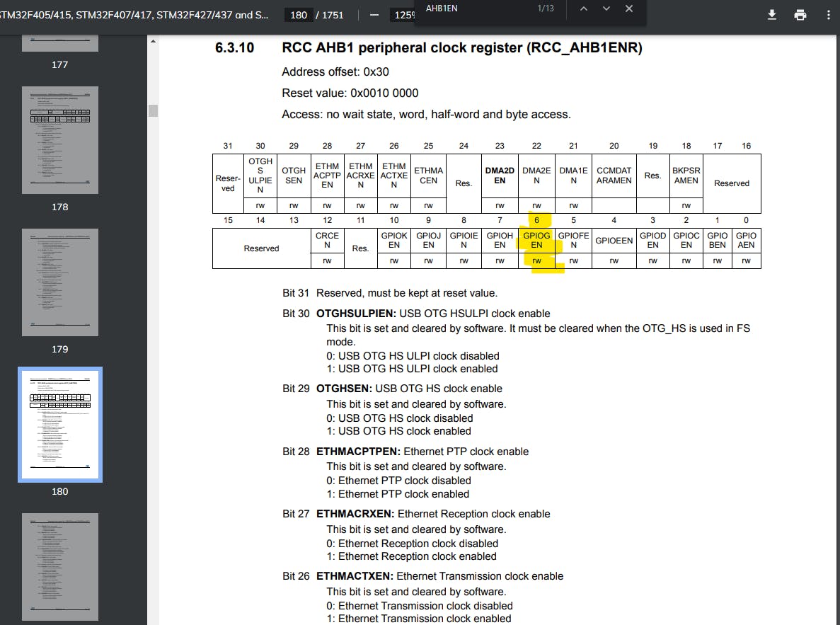
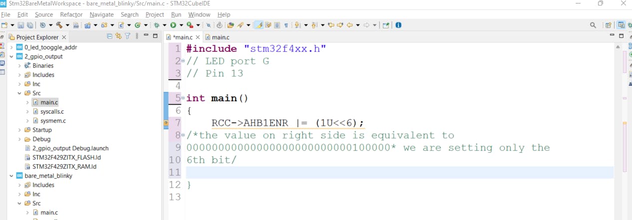
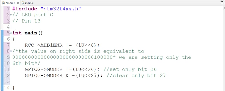
We can see that the 6th bit of the RCC AHB1 Peripheral Clock register is for the port G To enable the clock for the port G we will have to set the 6th bit of the register , we can do that by using
RCC->AHB1ENR |= (1U<<6); (RCC is a structure inside the header and AHB1ENR is a member inside it so we can access it using arrow operator) If you facing issues while understanding this operation, I would recommend to learn more about Bit Manipulation hackerearth.com/practice/basic-programming/..
Now that our port G has access to the clock let's set the mode of the PIN13
Search MODER in the Reference manual and open the GPIO Moder Register section
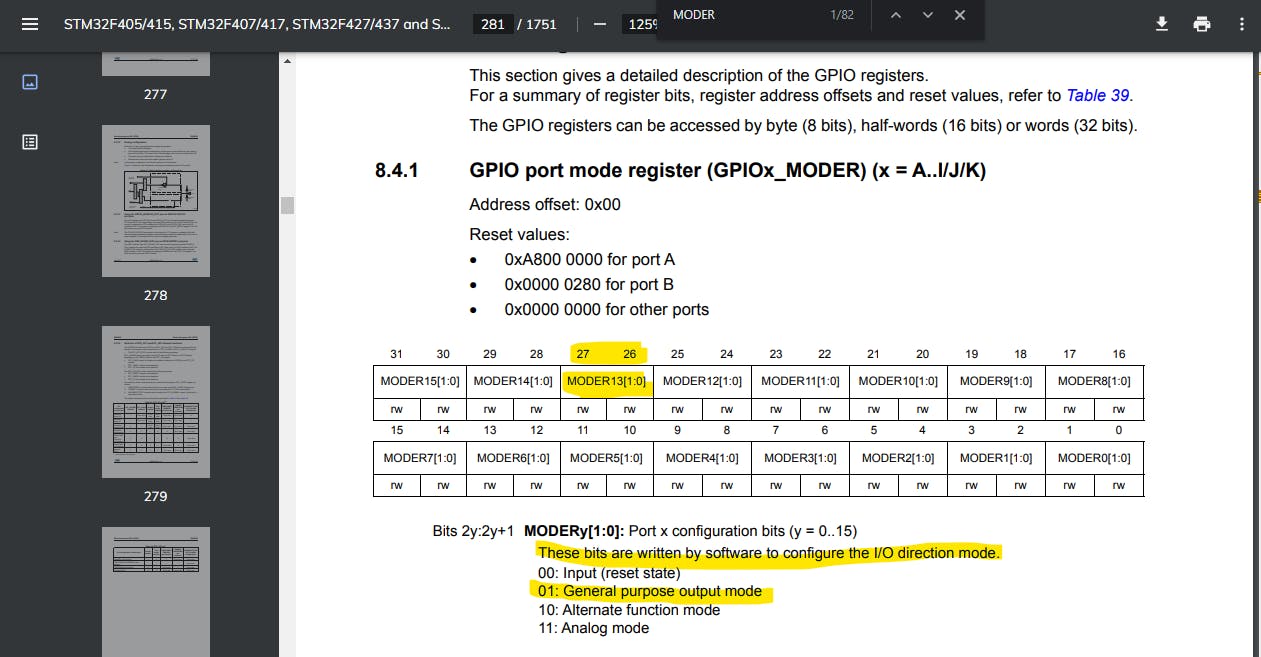
Our Pin number is 13 so the bits responsible to set the mode are 26 and 27
To set the Pin as OUTPUT we have to set 26th bit high and 27th bit low (check out pin configuration bits from the above image ) In code it will look like
GPIOG->MODER |=(1U<MODER &=~(1U<<27); //clear only bit 27 (MODER register is member of GPIOG structure so we can access it using the arrow operator )
Now it's time to blink the led, we want the led to keep blinking so we will make an infinite loop and toggle the data register of the pin inside that loop. To keep a time delay between the toggling of the LED we will use a for loop; while(1) { GPIOG->ODR ^= (1U<<13); for(int i=0;i<100000;i++){} }
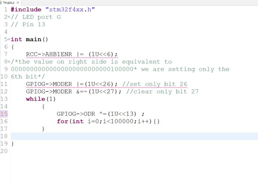
Now let's save and build the code !
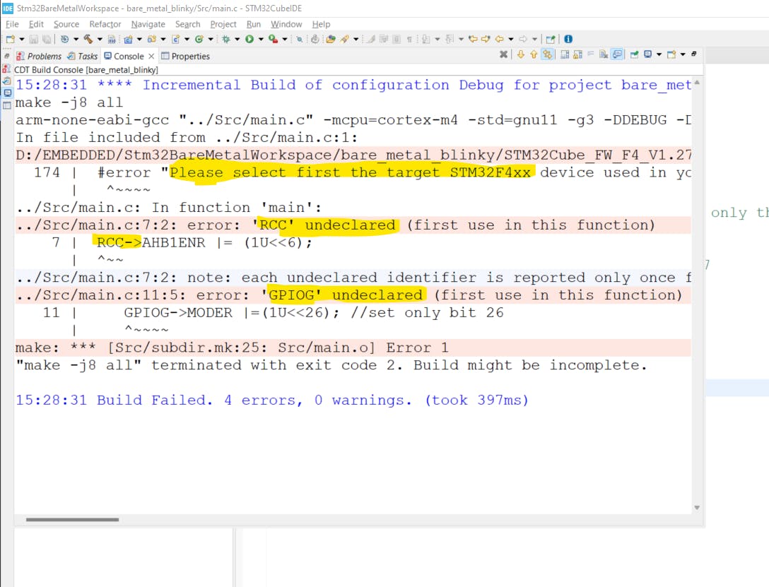
Uh!! There are 4 errors!!
Let’s fix it !
Lets understand the error
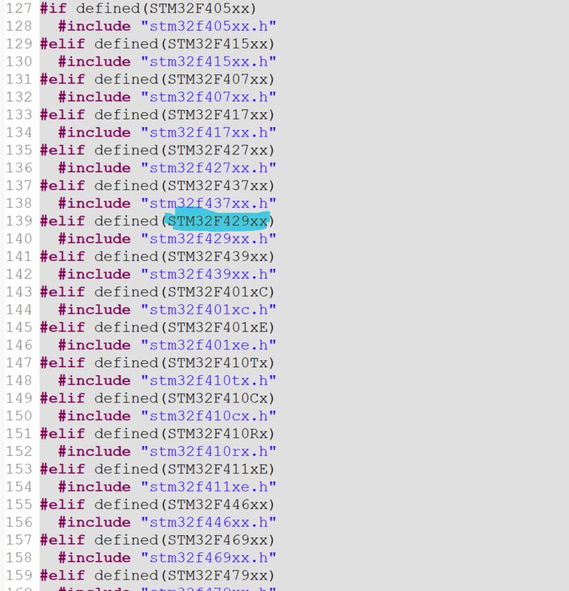
We have declared the header file using #include "stm32f4xx.h" at the start of the program but the header file does not know the exact serial number of our microcontroller yet.
Select the header file and press F3 key to open the stm32f4xx.h file
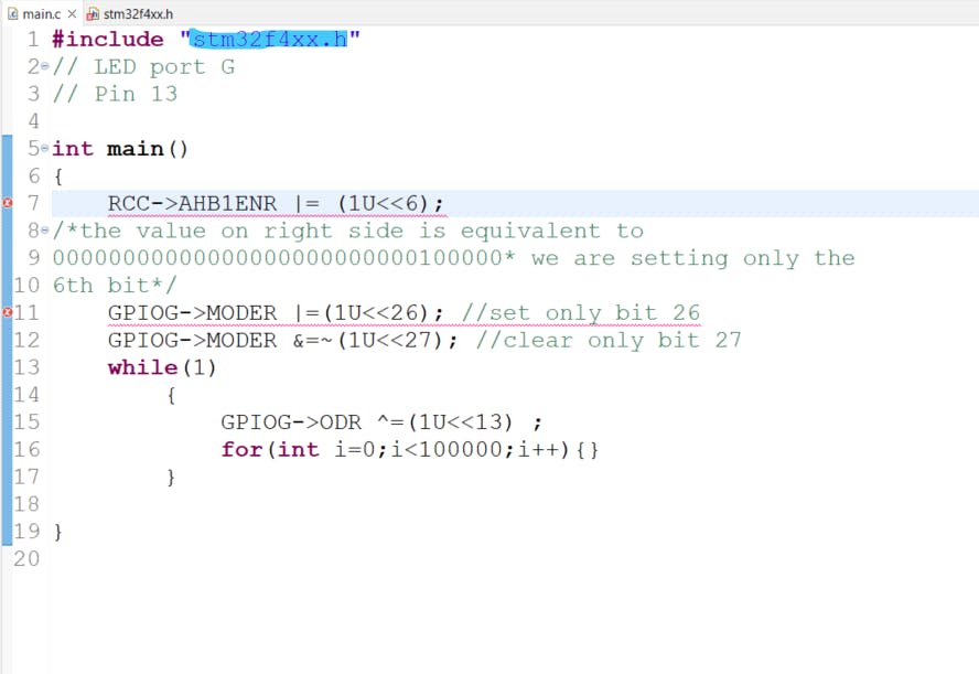
Copy the name of your microcontroller mine is STM32F429xx
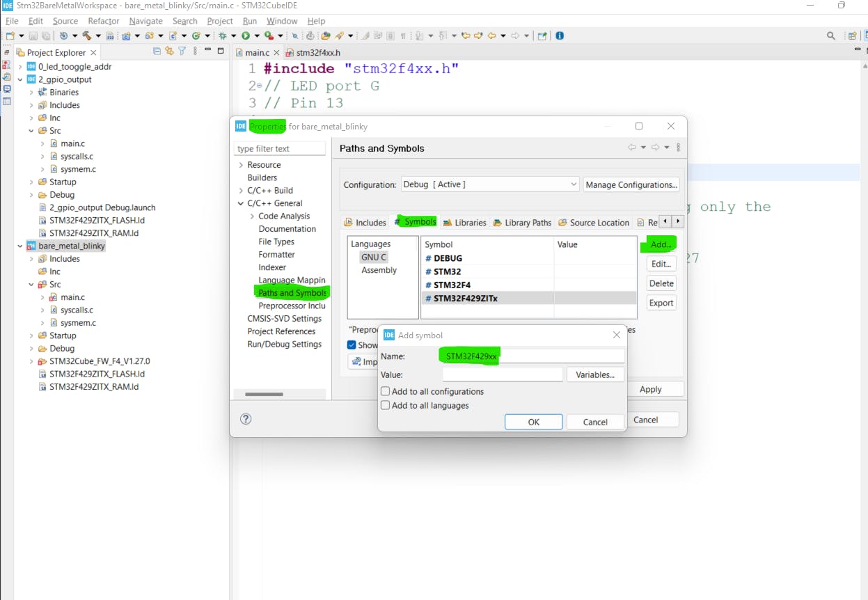
Go to properties again click Paths and Symbol, go to Symbols , click add, paste , click ok and then apply and close
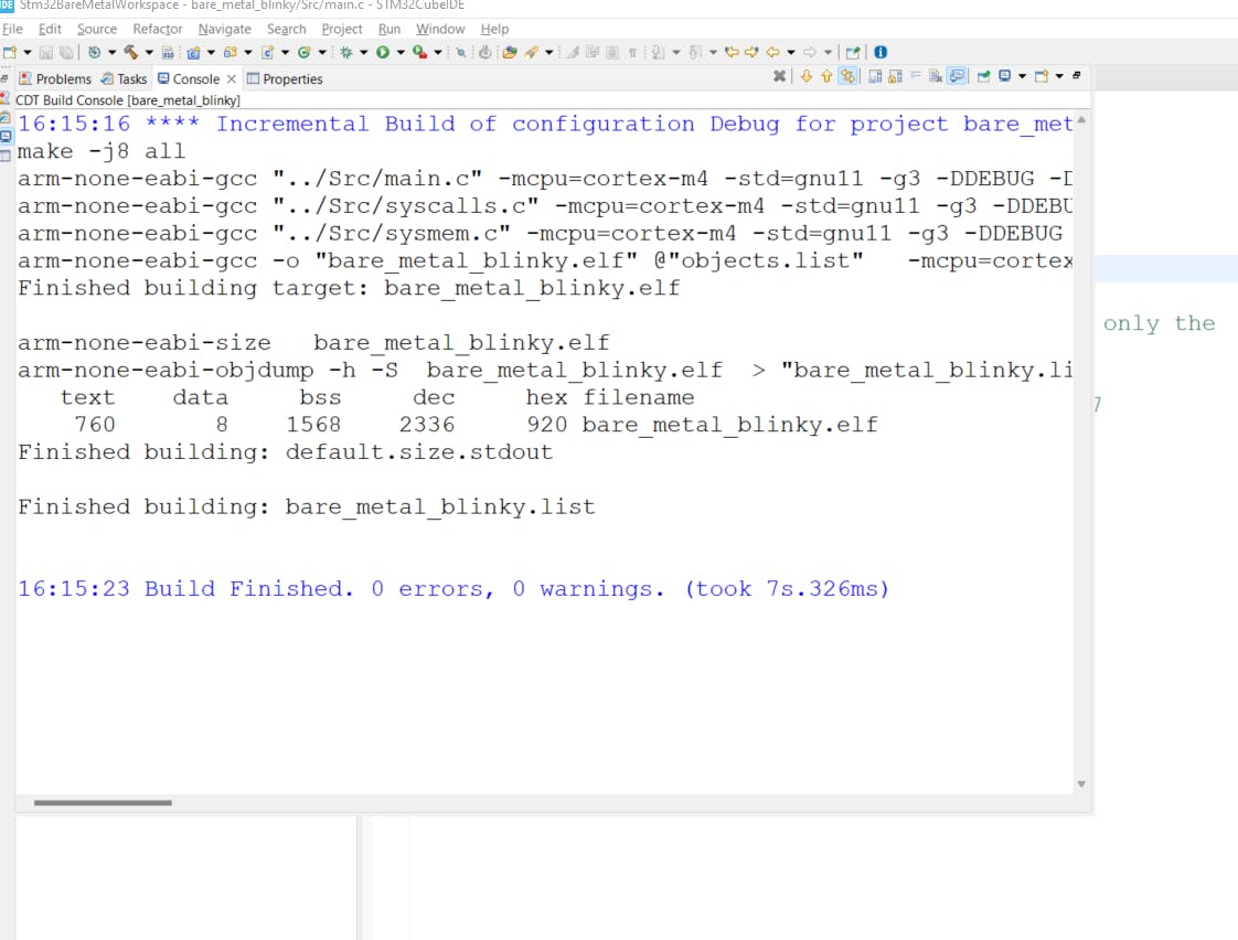
Build again and the errors should be gone now
To Upload the code connect the board to the PC via USB Click on Run button Then press ok
Done !!
Let me know if you are stuck somewhere in the comments ! Will be happy to help :)